
TPC65 - History: The PCB Age

Version 1.0

Even though the protoboard computer works, and I successfully worked with it for months, it has some significant drawbacks:

  • Difficult to modify
    • Making any changes to the system requires maneuvering through a trunk of wires with an iron.
  • Fragile
    • Multiple wires are often joined to a single pad. This requires the solder joint to be reheated/reflowed multiple times. A wire that pops loose would be difficult to reattach.
  • Not worth reproducing
    • It took about three days of soldering to get the computer connected. Repeating that task is not something I was looking forward to.
The obvious solution is to make a PCB version of the board. It always seemed kind of silly to me to make a PCB version of a one-off project. But, it's either that or doing it all by hand again. So, after following along with the excellent KiCAD tutorials by Shawn Hymel, I set out to put the computer onto copper. 

A tricky thing about computers of this era is managing the bus lines between devices. The most common approach I've seen is the X-Y approach, where you have traces run top-to-bottom on one side, and left-to-right on the other. This allows the traces to be a lot straighter with the trade-off of needing a lot more vias to connect the traces between layers.

Because I wasn't sure if this was even going to work (and because I'm cheap) I set out with the goal of making the PCB as cheap as possible to fabricate. This meant keeping the board to 100x100mm and two layers.

The first attempt was a direct copy of the hand-soldered computer, including all the mistakes made during construction:


The two boards shown above are functionally identical. Apart from one trace mistake, I only needed to move the components from board-to-board and it worked perfectly fine. 
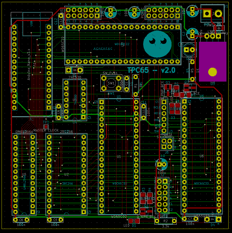

Version 2.0

The next step was to finally commit the improvements I wanted to make on the original computer. These improvements included:
  • Fixing the mistakes made during construction
    • Specifically aligning the bus lines with the Arduino Nano's ports for faster bitwise operations.
  • Adding a second VIA
  • Adding a dedicated SD card port
    • Utilizes port A of the first VIA

 And this, version 2 was born:


Version 3.0

As of writing, I'm currently working on the next version of the computer which will replace the 65C02 with a 65C816, the 16-bit successor to the 6502.

In the next post, I'll detail more about the theory of operation of these computers and the supporting software.

Comments

  1. Hello
    I came across your blog and was deeply impressed by your content, which I believe is of great value to electronic enthusiasts.

    This is Liam from PCBWay, I would love to sponsor your project by providing free PCB prototyping. In return, I only ask for a slight promotion or a review about the quality or service you receive.

    Would you be interested in partnering up? Contact me: liam@pcbway.com

    ReplyDelete

Post a Comment

Popular posts from this blog

TFORTH

Overview TFORTH is my custom version of FORTH. It started as a programming exercise that grew into a somewhat usable language. This version of FORTH is a bit odd in that it has no compiling mode at all . Not even bytecode compiling. Everything is 100% interpreted. So, it's essentially a fancy text parser. It also doesn't try to be ANSI compliant at all. That being said, it does support a lot of common FORTH things like you would expect, including: custom function definitions, calling external functions via function pointers, full access to the system's memory map, input/output, etc.   Variables There are some big differences, under-the-hood, with this version of FORTH. For one, there are no variables. Instead, I define variables as functions with a index to the "variable page," a page in memory dedicated to temporary storage. So, for example,    5 0 ! would assign the literal value 5 to index 0 in the variable page. So, to declare a "variable," I would d...

TPC65 - History: breadboards and protoboards

Since I was a teenager, something I've always wanted to do was design and build a computer, chip-by-chip. I was inspired by the movie Pirates of Silicon Valley, specifically when Steve Wozniak built a computer, the Apple 1, that started an empire. So, I started learning electronics with the main goal of making my own computer.   Breadboard Shenanigans   In 2018, I finally got around to working with the legendary 6502 CPU and built my first rudimentary computer that barely worked. This version of the computer relied on an Arduino Mega to act as an EEPROM and serial interface. Thus, the entire computer needed to be synchronized to the Arduino to function. Unfortunately, building computers on breadboards is a pretty frustrating task. Breadboards are prone to manufacturing defects that can cause intermittent shorts between components, intermittent connections between the breadboard and components, massive amounts of parasitic capacitance and inductance. All of which are incre...

TPC65 - Arduino Optimization

One feature/limitation of my computer design is that it uses an Arduino to replace a lot of extra logic and interface components. Specifically, the Arduino performs the following functions: Serial I/O The computer piggy-backs off of the Arduino's built-in serial to USB interface chips to communicate with the host laptop. Power-up reset circuitry The 6502 needs to run for 50 or so full clock cycles with the RESET line held low, and then RESET is sent high for normal operation. System clock Because the computer uses the Arduino's USB interface, the Arduino must be kept synchronous to the computer. If the computer runs too quickly, it could outpace the Arduino's ability to read and send data.   The last point is the most important of all. The Arduino must be kept in lock-step with the computer at any given time in order to ensure that I/O data isn't missed. Thus, the the clock output is just a digital output from the Arduino. This means that the computer's maximum spee...